Diaphragm Walls help improve Infrastructures
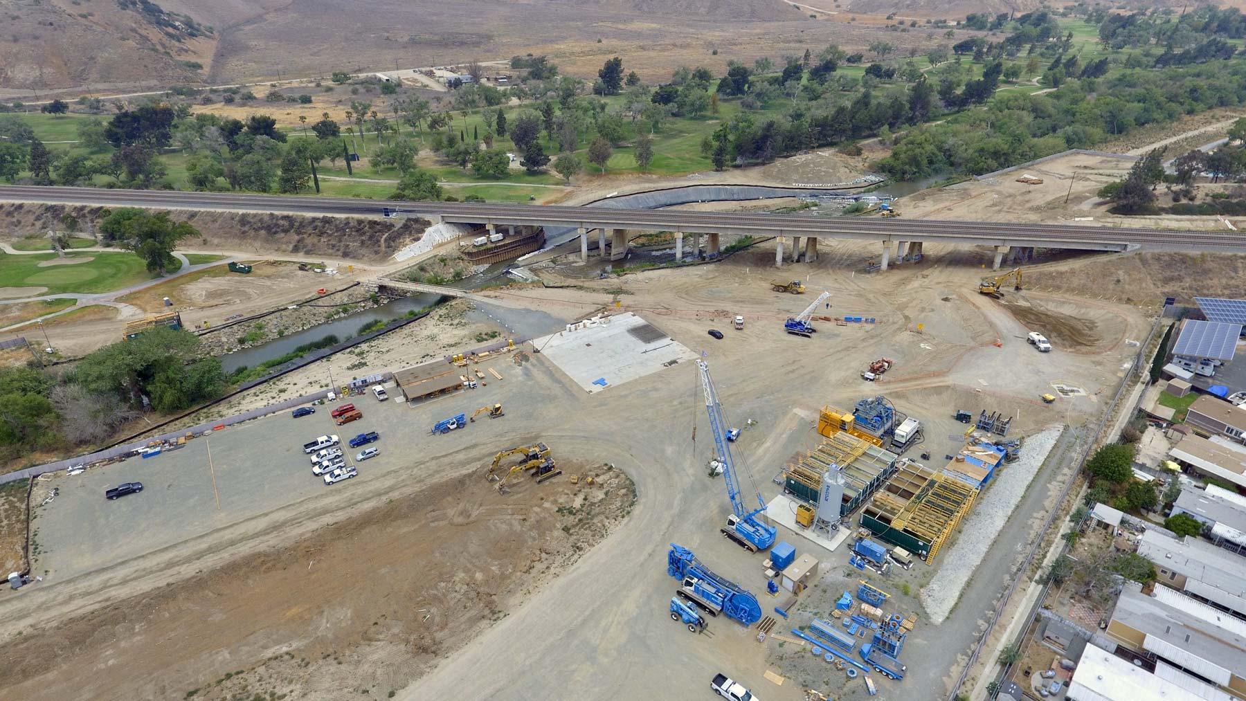
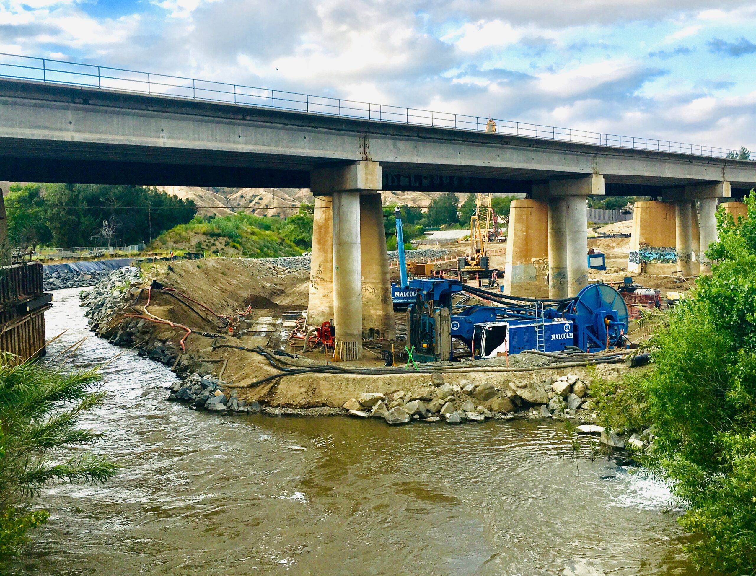
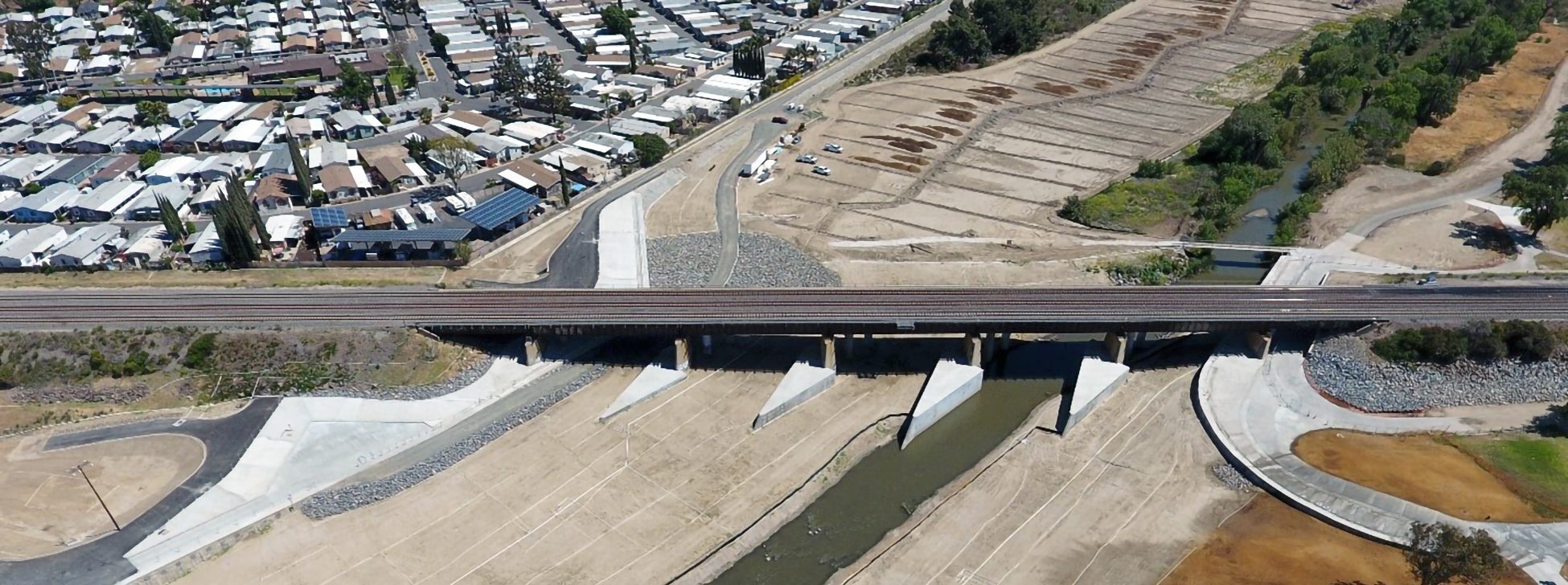
The Santa Ana River is designed to improve the scour protection of the BNSF Railway Bridge foundations, during large discharges of the Prado Dam, located one mile upstream from the project site. Originally the BNSF Bridge was designed to withstand scour depths of 14 feet however due to the Prado Dam being modified to handle larger discharge flows, deeper scour has the potential to occur. The existing railroad bridge supports over 80 freight and passenger trains daily, making project coordination even more challenging.
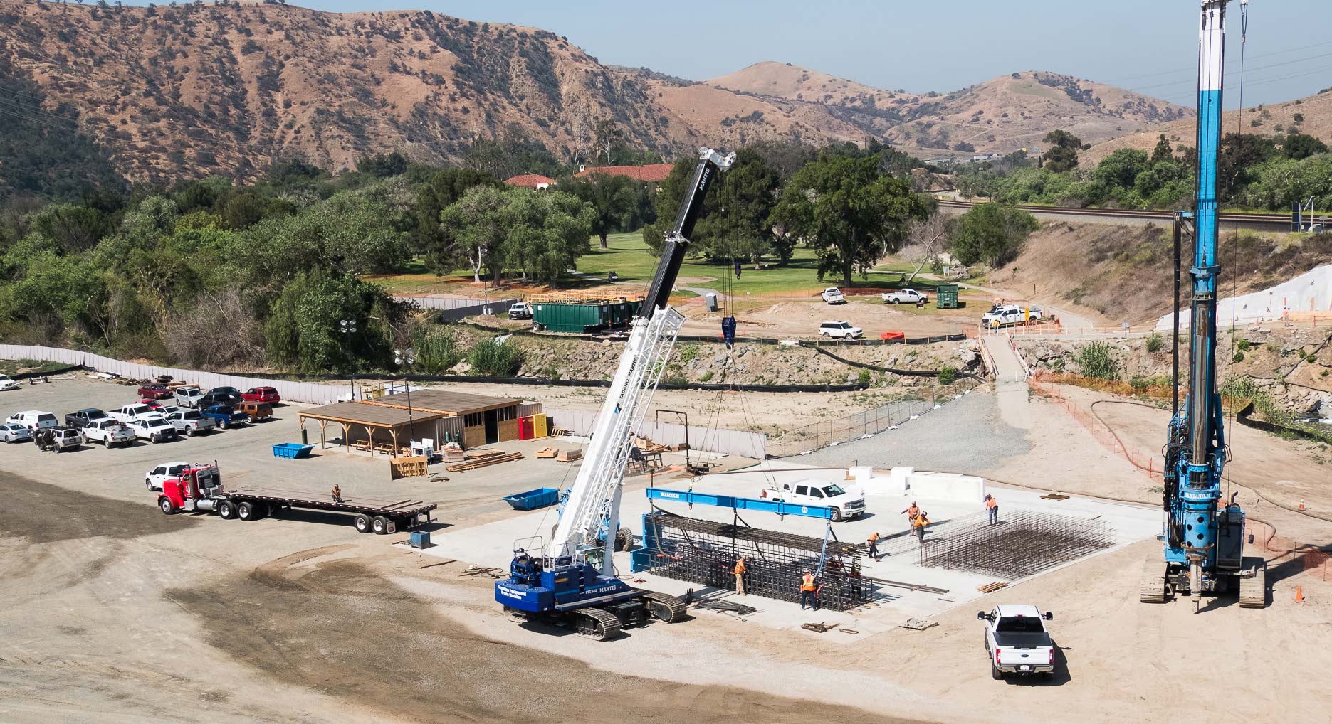
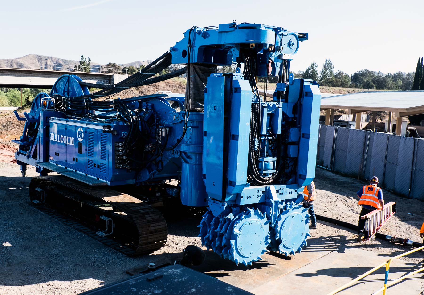
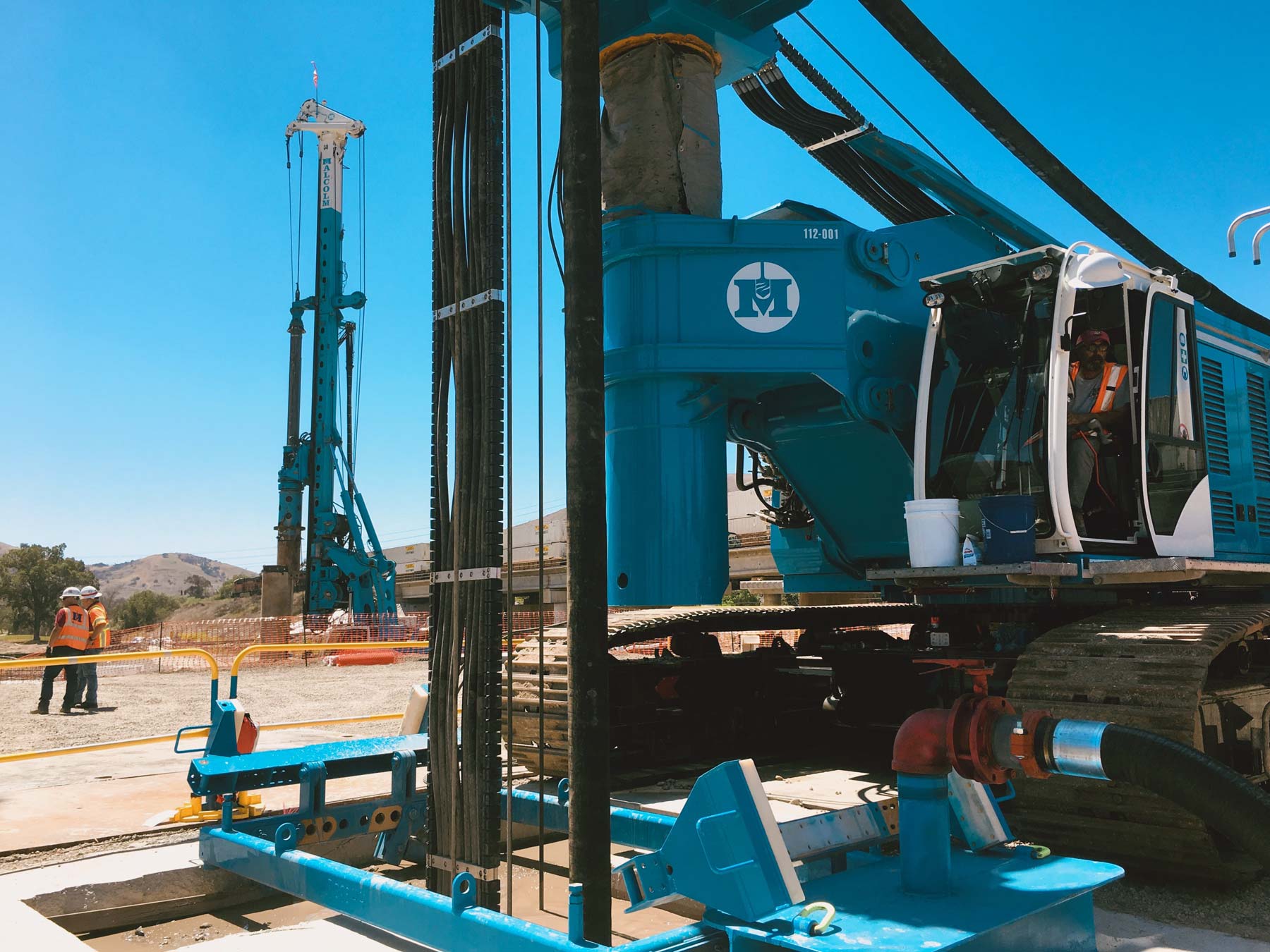
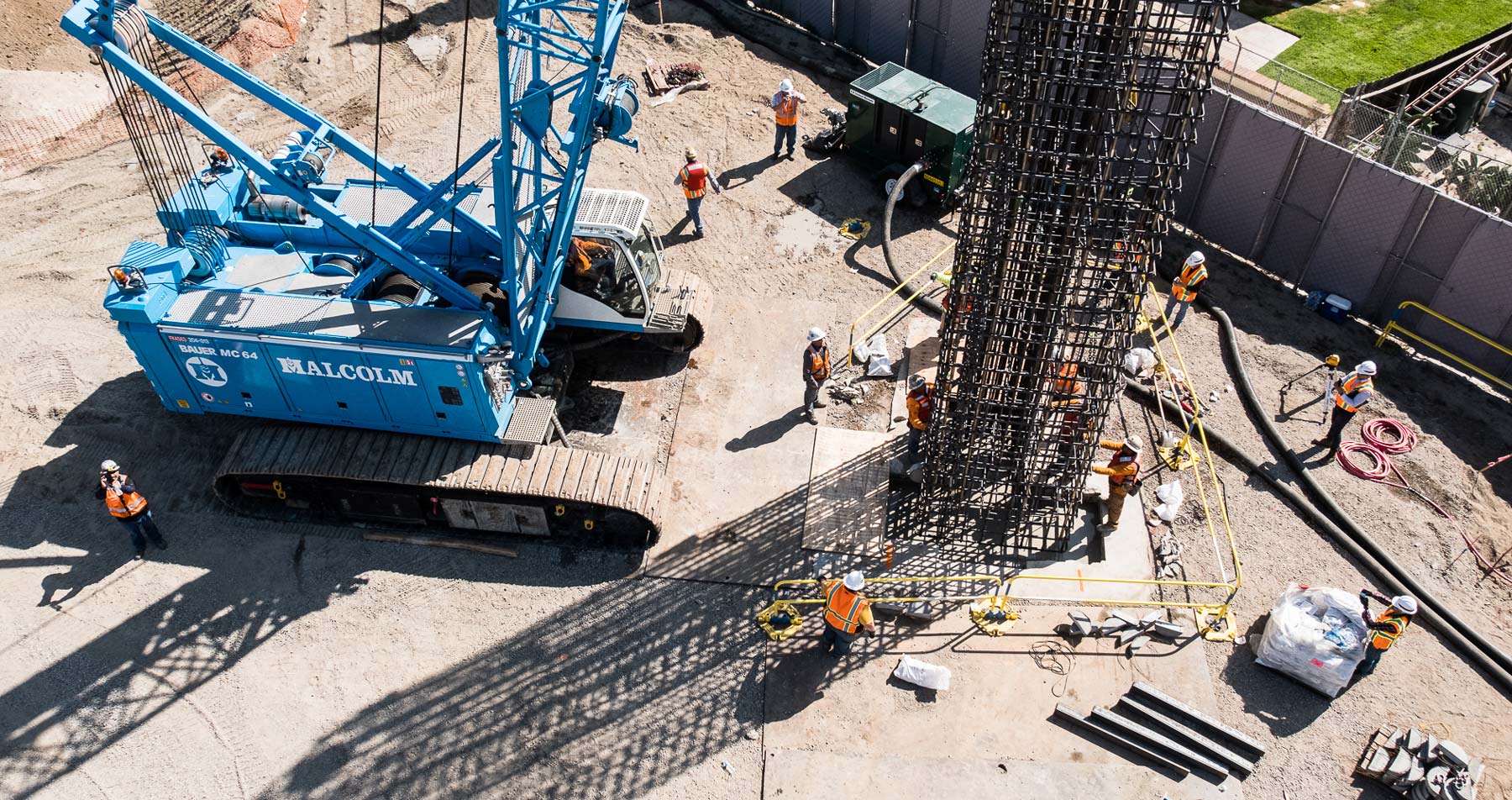
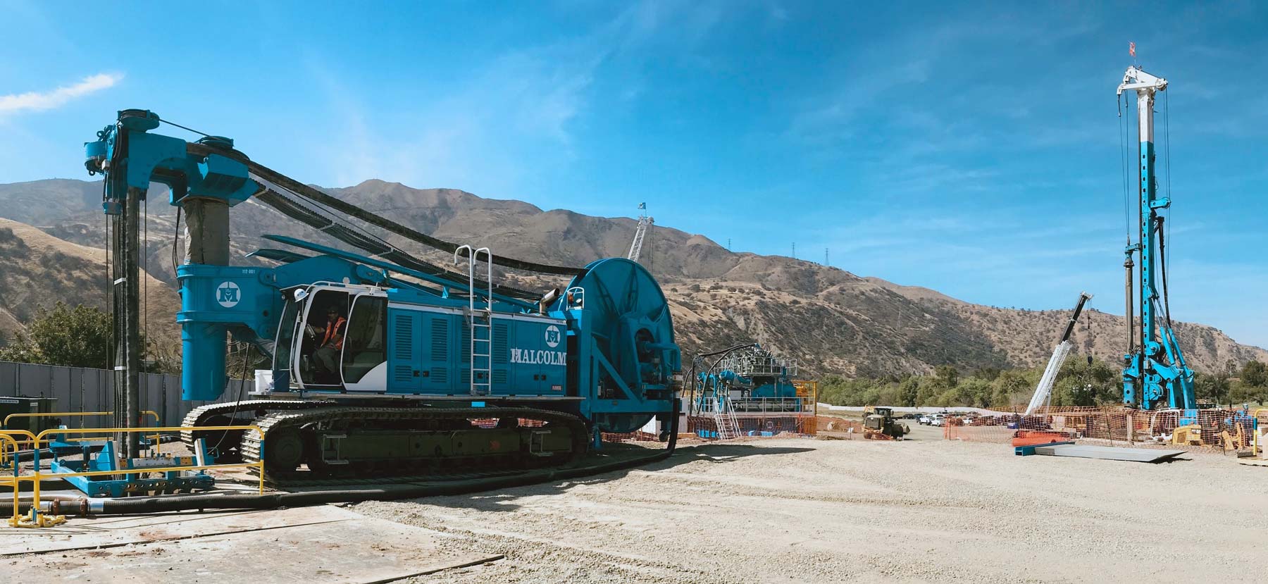
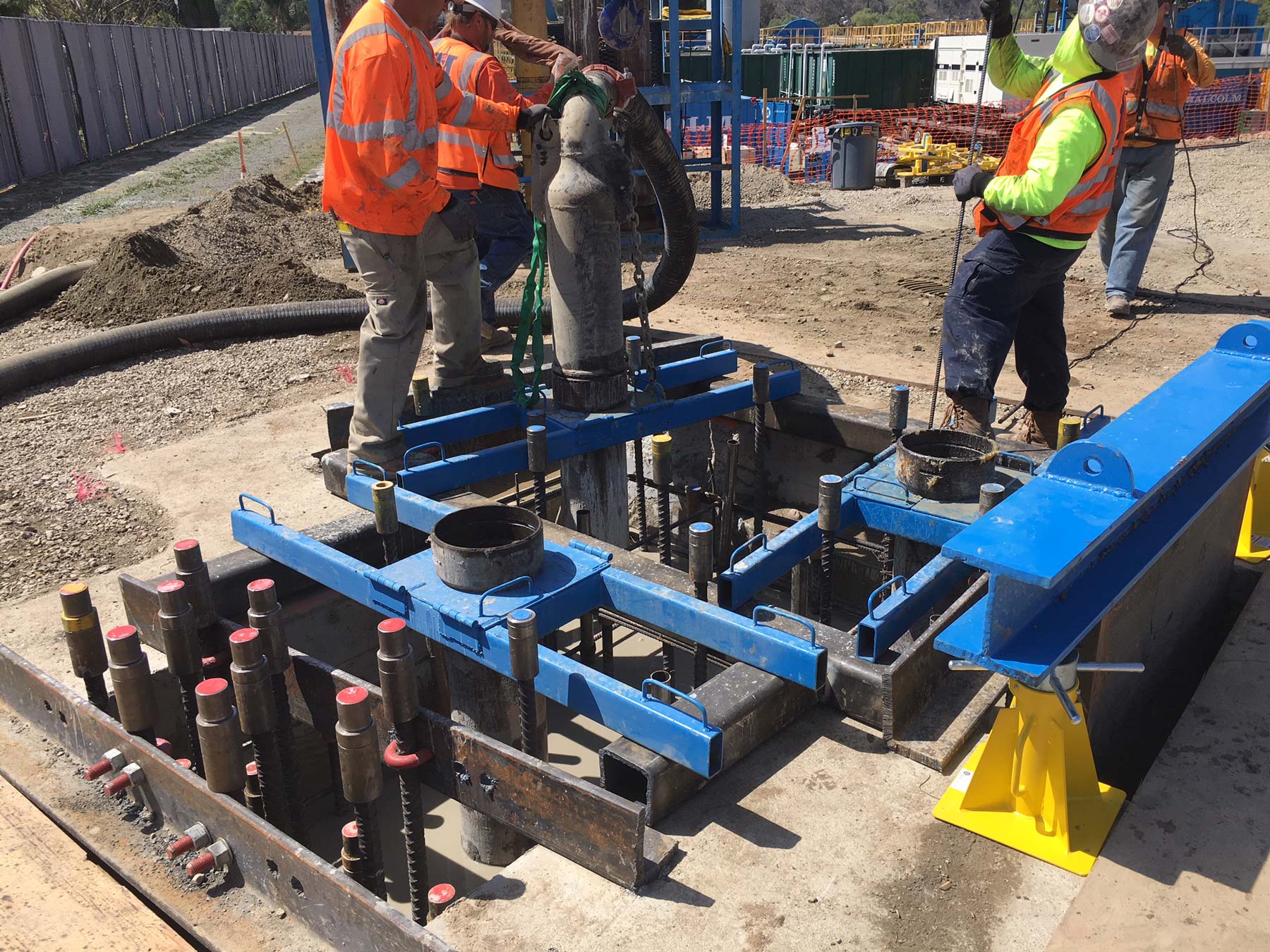
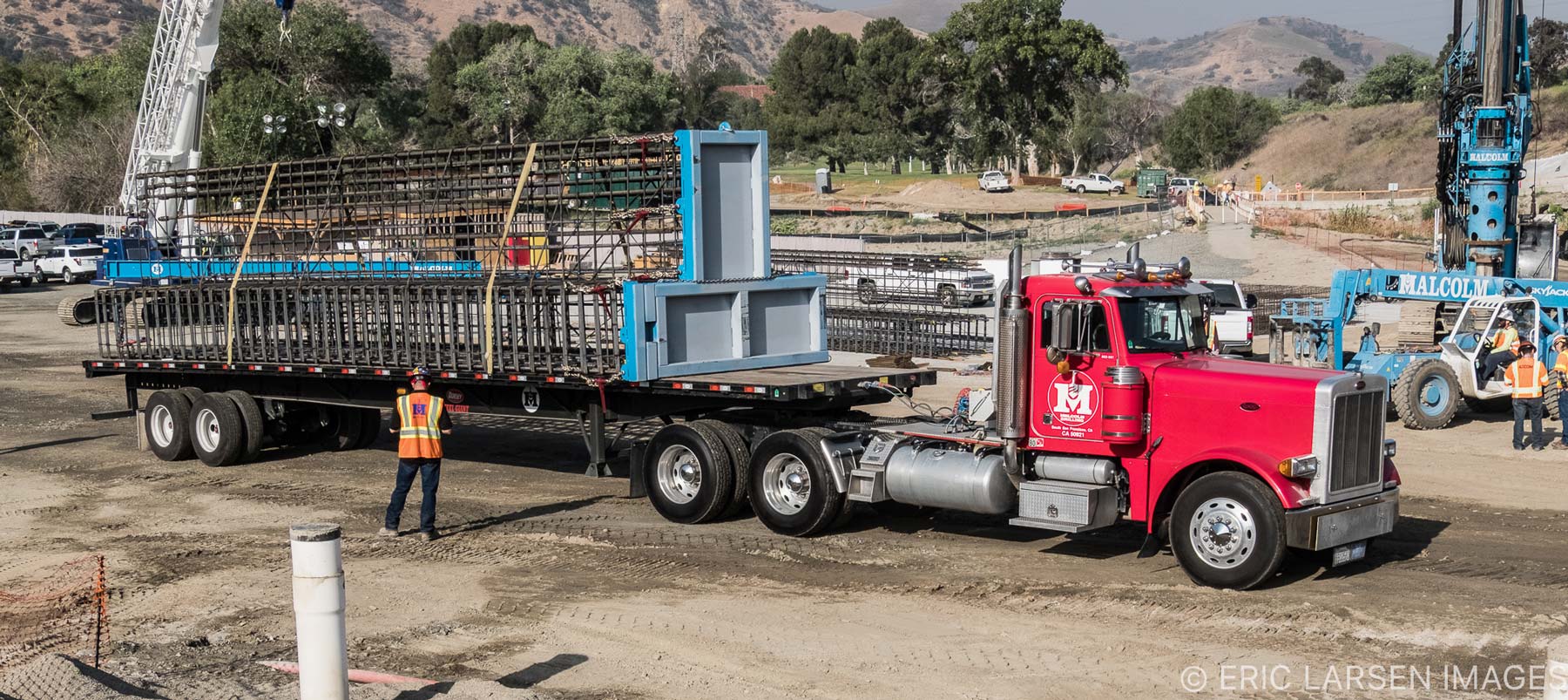
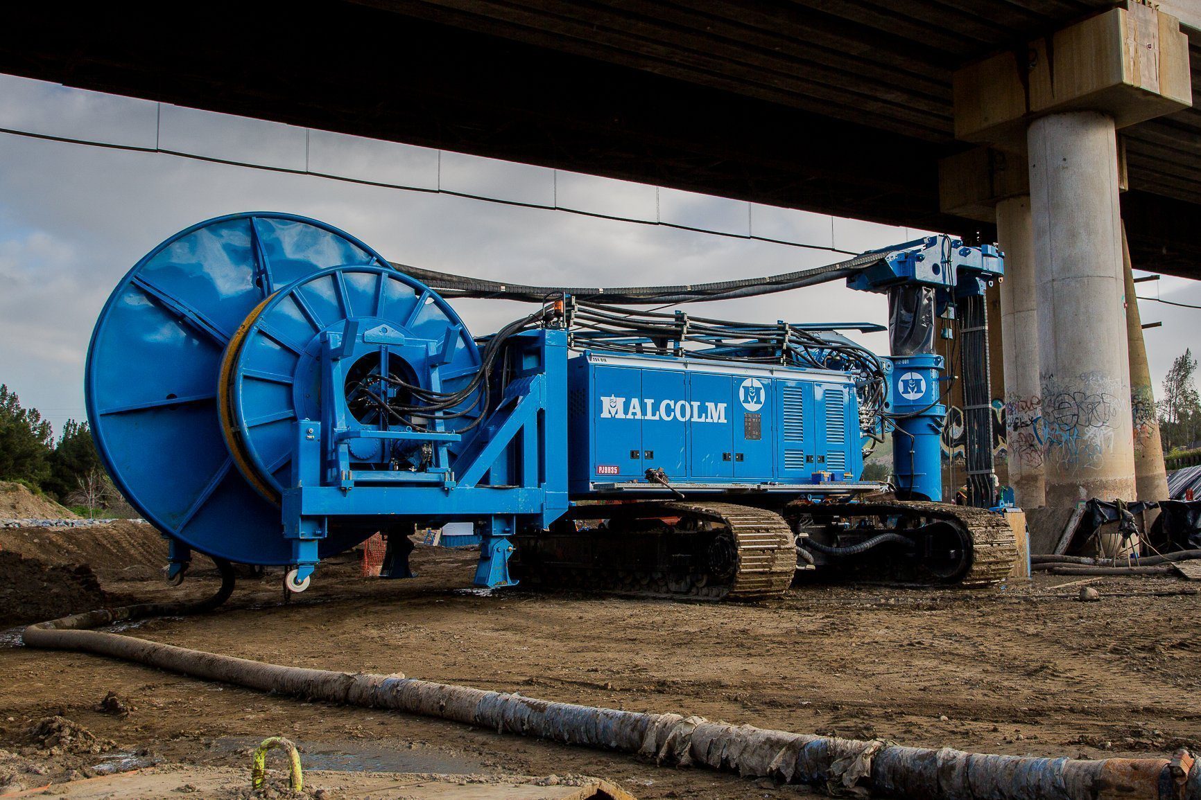
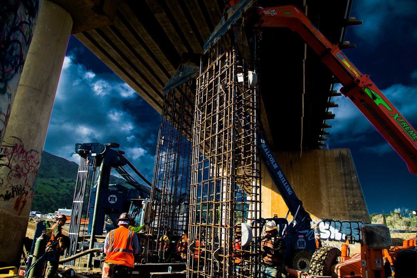
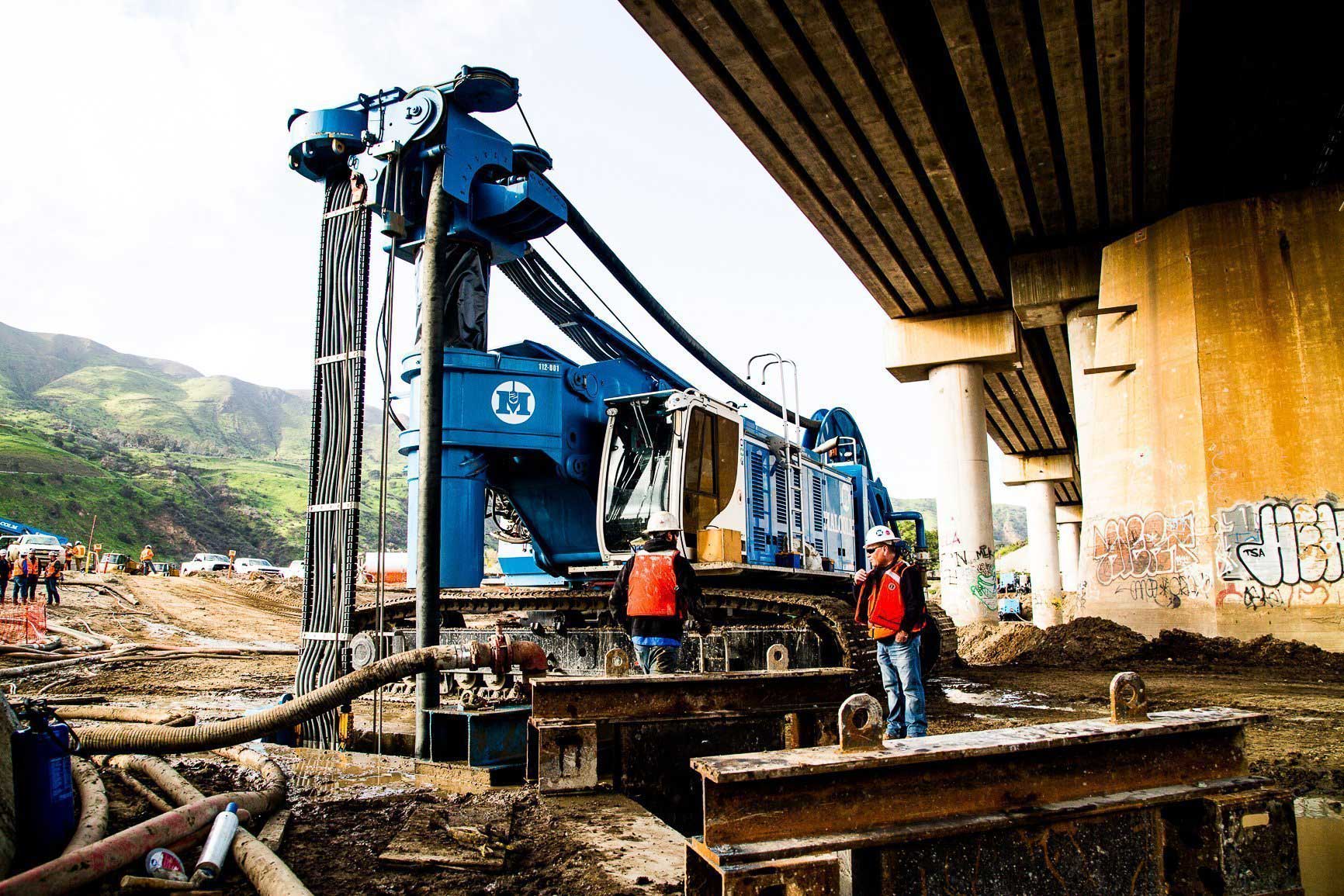
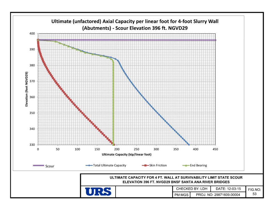
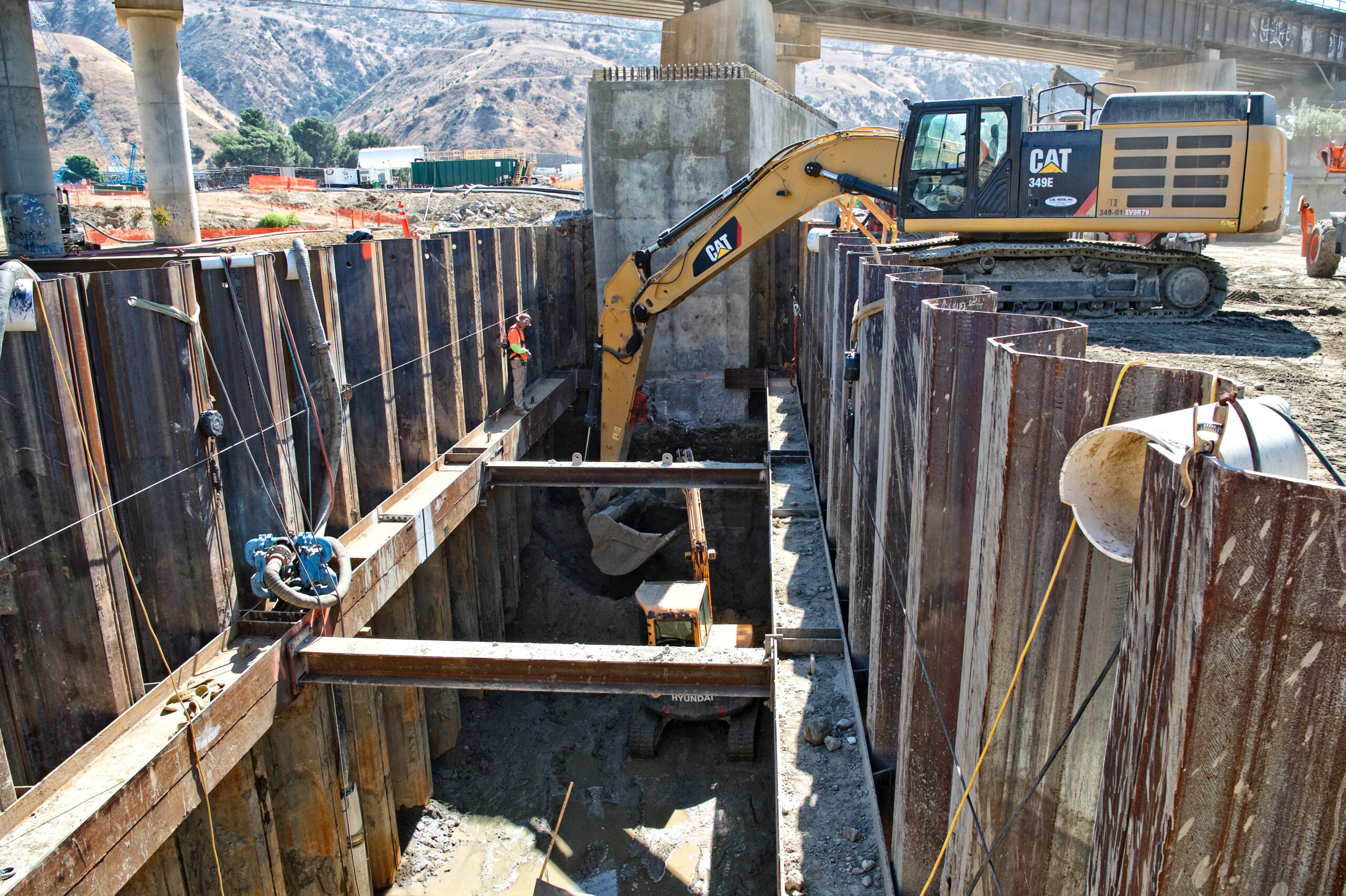
The protection design for the bridge consists of slurry concrete diaphragm walls surrounding piers #2 to #5, with the same technique being applied at the East and West abutments. The diaphragm walls for the abutments include challenging T Panels designed as cantilever walls due to the proximity to the existing bridge foundations. These concrete diaphragm walls also serve as Load Bearing Elements (LBE), with ultimate axial capacity exceeding 300 kips per linear foot. The railroad bridge had to remain active during construction therefore work was performed from underneath the bridge with overhead clearances of only 28-30 feet. A specially designed low-overhead hydrocutter was employed to excavate panels to depths of approximately 100 feet. To accommodate the bridge overhead restrictions, rebar cages were designed and constructed in shorter sections, each no longer than 20 feet.
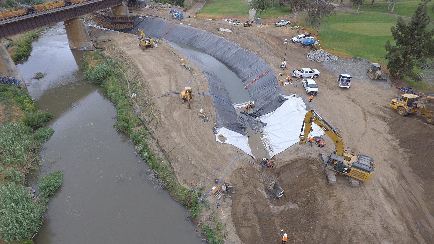
The Santa Ana River was temporarily diverted for about 18 months to facilitate the commencement of pier protection, and diaphragm wall construction.
Malcolm Drilling, Malcolm International, and Bauer JV (MMB), and the Corps worked collaboratively to design the individual diaphragm wall panels. Approximately 50% of the work had to be installed beneath the existing bridge structure, a special low-overhead hydrocutter was used for the project construction.
The diaphragm wall panels reached depths of up to 100 feet, and while their lengths varied slightly, they were generally between 9 and 21 feet wide and 4 feet thick. The diaphragm wall design included tie-backs at each abutment. In areas where tie-backs couldn’t be installed, reinforced concrete T-shaped diaphragm wall panels were used. During the construction of the diaphragm walls, the below-grade sections of the T panels were built, and the above-grade sections were formed as CIP concrete walls. Diaphragm wall rebar was coupled with CIP wall rebar.
As a result of extensive planning, preparation, and execution, the work areas were able to be quickly restored during any major weather events, specifically flooding, to allow work to continue. Daily weather and river conditions were always assessed and monitored consecutively using multiple tools, including constant contact with the dam operators. The project team worked very hard to establish an Emergency Action Plan with all stakeholders to reduce risk for all parties and always ensured the safety for personnel.
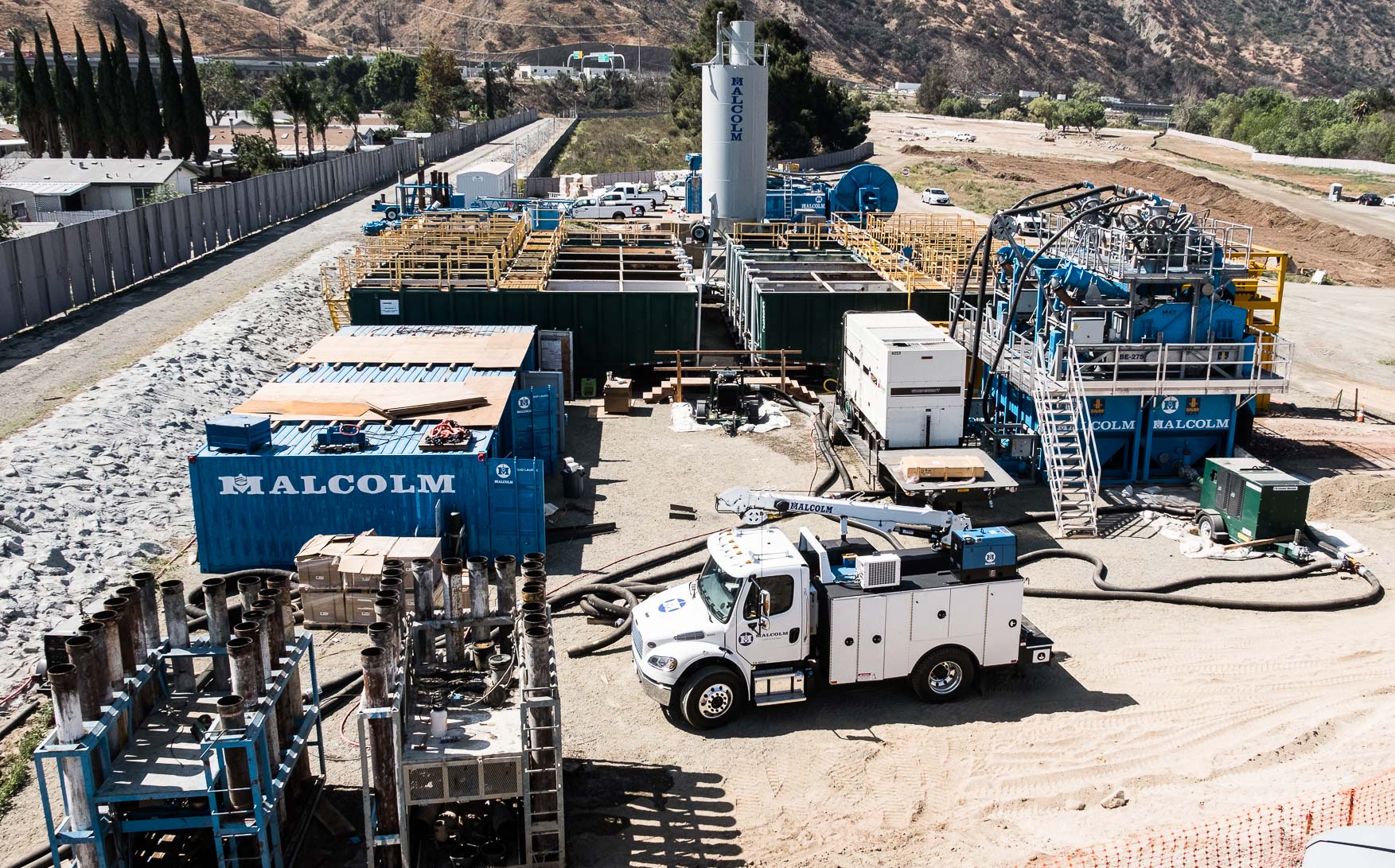
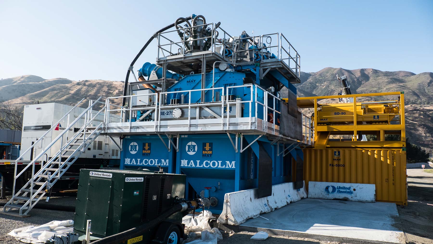
Technical challenges included the excavation of the diaphragm wall in the existing riverbed, which contained subsurface conditions with layers of sand, gravel, cobbles, and boulders. The integrity of all diaphragm wall panels was assessed through Crosshole Sonic Logging (CSL) for acceptance. Excellent quality control measures were applied on all work phases, from excavation verticality over support fluid preparation, placement of concrete on rebar and tremie, and ensuring the highest standards are being upheld.
This project was a joint venture between Malcolm Drilling, Malcolm International, and Bauer Foundations.